
GM Squarebody Wheelbase & Chassis Blueprint Dimensions
Factory frame dimensions, bed lengths, cab-to-axle (CA) measurements, and frame cut formulas for 1973–1987 Chevrolet and GMC C/K third-generation trucks.
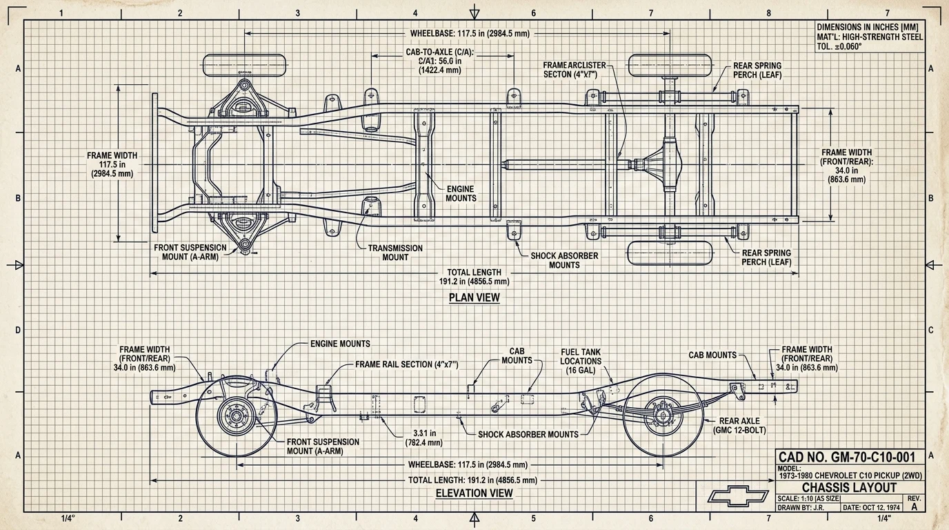
Chassis Wheelbase & Dimensional Resolver
Select any factory chassis platform to load exact wheelbase, overall length, bed dimensions, and frame section modulus.
Factory Wheelbase & Frame Rail Dimension Matrix
| Model Series | Wheelbase | Overall Length | Cab-to-Axle (CA) | Bed Length | Frame Rail Dimensions |
|---|---|---|---|---|---|
| C10 / K10 Short Bed Sec 2A, p. 4GM Service Manual ST-330Sec 2A: 117.5" SWB Blueprint Tram Gauge Spec: 0.125" max | 117.5 in | 191.3 in | 42.0 in | 6.5 ft (78.8") | 6.00" × 2.30" × 0.156" |
| C10 / K10 Long Bed Sec 2A, p. 6GM Service Manual ST-330Sec 2A: 131.5" LWB Blueprint Tram Gauge Spec: 0.125" max | 131.5 in | 211.3 in | 56.0 in | 8.0 ft (98.0") | 6.00" × 2.30" × 0.156" |
| C20 / K20 Long Bed Sec 2A, p. 8GM Service Manual ST-330Sec 2A: 3/4-Ton Heavy Frame Web Depth: 7.00 in | 131.5 in | 211.3 in | 56.0 in | 8.0 ft HD (98.0") | 7.00" × 2.50" × 0.187" |
| C30 / K30 Standard Sec 2A, p. 12GM Service Manual ST-330Sec 2A: 1-Ton Chassis Standards Web Depth: 8.00 in | 131.5 / 135.5 in | 212.5 in | 56.0 / 60.0 in | 8.0 ft HD Dually | 8.00" × 2.75" × 0.218" |
| C20/C30 Crew Cab Sec 2A, p. 16GM Service Manual ST-330Sec 2A: Crew Cab 164.5" Blueprint Section Modulus: 5.75 in³ | 164.5 in | 244.3 in | 56.0 in | 8.0 ft Bed | 7.50" × 2.50" × 0.187" |
| K5 Blazer / Jimmy Sec 2A, p. 2GM Service Manual ST-330Sec 2A: K5 106.5" SUV Blueprint Frame Boxed Front Horns | 106.5 in | 184.8 in | 31.0 in | Enclosed Cargo | 6.00" × 2.30" × 0.156" |
| Suburban C/K Sec 2A, p. 14GM Service Manual ST-330Sec 2A: Suburban 129.5" Blueprint Extended Rear Overhang | 129.5 in | 219.1 in | N/A | 3-Row Enclosed | 6.50" × 2.50" × 0.187" |
Long Bed to Short Bed Frame Shortening Formula
Converting an abundant 131.5" long bed chassis into a desirable 117.5" short bed requires cutting a precise 14.0 inches from the middle frame span and 6.0 inches off the rear frame tails:
Chassis Metallurgy, Boxing Plates & Body Alignment Standards
Factory 1973–1987 GM truck frames utilize cold-formed carbon steel C-channel rails with a minimum yield strength of 32,000 to 36,000 PSI. Half-ton C10 rails feature an open-channel design engineered to flex under torsional loading. When increasing horsepower beyond 400 HP or performing suspension lowering, installing full-length steel boxing plates between the cab mounts and rear axle arch increases torsional rigidity by over 300%.
Whenever shortening or repairing a chassis, continuous vertical welds across the rail are strictly forbidden by GM engineering standards due to heat-affected zone crystallization. All frame joints require 45-degree angle cuts reinforced with diamond-shaped internal or external fishplates extending at least 3 inches past each weld seam.
Accurate body panel alignment requires squaring the bare chassis prior to cab reinstallation. Diagonal measurements taken between symmetrical factory reference tooling holes in the front crossmember and rear spring hanger brackets must agree within 1/8 inch (3.18 mm) across the full wheelbase span.
Frequently Asked Wheelbase & Dimension Questions
01 What is the wheelbase of a short bed vs long bed Squarebody C10?
A standard short bed (SWB) 1973–1987 Chevrolet C10 or GMC 1500 pickup features a 117.5-inch wheelbase with a 6.5-foot bed. A standard long bed (LWB) pickup features a 131.5-inch wheelbase with an 8.0-foot bed. Overall vehicle length is 191.3 inches for short beds and 211.3 inches for long beds.
02 How much frame must be cut to convert a long bed Squarebody to a short bed?
Converting a 131.5" long bed frame into a 117.5" short bed requires cutting exactly 14.0 inches out of the middle frame section directly beneath the cab-to-bed gap (or staggered Z-cut) and cutting 6.0 inches off the rear frame horns behind the rear spring hangers to align with the short bed rear bumper mounts.
03 What is the cab-to-axle (CA) measurement across GM Squarebody models?
Cab-to-axle (CA) distance measured from the back of the cab sheet metal to the rear axle centerline is 42.0 inches on 117.5" SWB pickups, 56.0 inches on 131.5" LWB pickups, 60.0 inches on 135.5" commercial Cab & Chassis models, and 84.0 inches on 159.5" heavy commercial platforms.
04 What is the frame rail steel thickness and section modulus on C10 vs C30?
Half-ton C10 frames utilize 0.156-inch (5/32") carbon steel with a 6.00" channel web and section modulus of 3.84 in³. Heavy-duty C30 one-ton dually frames utilize 0.218-inch (7/32") high-tensile 32,000 PSI steel with an 8.00" web height and section modulus of 5.75 in³.
Steering Box Ratios & Rag Joint Spline Guide
Distinguish factory 4-turn standard boxes from 3-turn variable boxes, and navigate the critical 1976/1977 rag joint input spline and fitting transition.
- Standard Saginaw 800 (4.0 Turns Lock-to-Lock): Constant 17.5:1 ratio. Factory equipped on base C10/K10 and all heavy-duty C20/C30 trucks. High mechanical leverage for heavy loads with zero center twitchiness.
- Quick-Ratio Variable Saginaw (3.25 to 3.5 Turns): 16:1 on-center transitioning to 13:1 off-center. Delivered on Scottsdale/Silverado packages and shortbed sport trucks for crisp parking maneuverability.
- Modern Fast-Ratio Retrofit (2.75 Turns Lock-to-Lock): Direct-bolt swap using 1993–1998 Jeep Grand Cherokee (JGC) Saginaw box or Monte Carlo SS 12.7:1 box. Requires metric O-ring adapters or a 1977+ steering column rag joint.
- 1973–1976 Early Architecture:
13/16"-36spline input shaft. Hydraulic ports utilize 45° SAE inverted flare fittings (5/8"-18 pressure, 11/16"-18 return). Uses Borgeson 000920 or Dorman 31011 flex coupler. - 1977–1987 Late Architecture:
3/4"-30spline input shaft. Hydraulic ports switched to Saginaw metric O-ring fittings (M16x1.5 pressure, M18x1.5 return). Uses Lares 201 or Dorman 31014 flex coupler. - Coupling Pinch Bolt Spec: 7/16"-14 12-point or hex grade-8 bolt torqued to 30 lb-ft (41 N·m). Pinch bolt must pass through input shaft relief groove.
Squarebody Engineering Architecture & Technical Pipeline
Complete subsystem hierarchy modeling powertrain, drivetrain ratios, factory electrical, and Phase 2 sister tools.
Powertrain & Small/Big Block Engine Specs
CID, horsepower, compression ratios, firing order, and valvetrain tolerances for 250, 305, 350, 400, and 454.
Automatic & Manual Transmission Ratios
TH350, TH400, 700R4, and SM465 continuous highway RPM, gear ratio, and rolling tire diameter solver.
Universal 13/17-Digit VIN & SPID RPO Decoder
ISO 3779 dual-format decoder for model year, assembly plant, GVWR series, and factory options.
Factory Electrical & Bulkhead Wiring Pinouts
1973-1987 firewall bulkhead connector pinouts, GM color standards, wire gauges, and ignition circuits.