
GM Squarebody Suspension Lift & Drop Geometry Guide
Engineering tolerances for lowering C10 pickups (spindles, flip kits, C-notches) and lifting 4WD K10/K20 platforms (leaf arch, driveline shims, crossover steering).
Ride Height & Geometry Configuration Solver
Select any suspension setup to inspect component requirements, tire clearances, driveline angle modifications, and frame cutting needs.
C10 2WD Lowering Mechanics: Spindles vs. Flip Kits
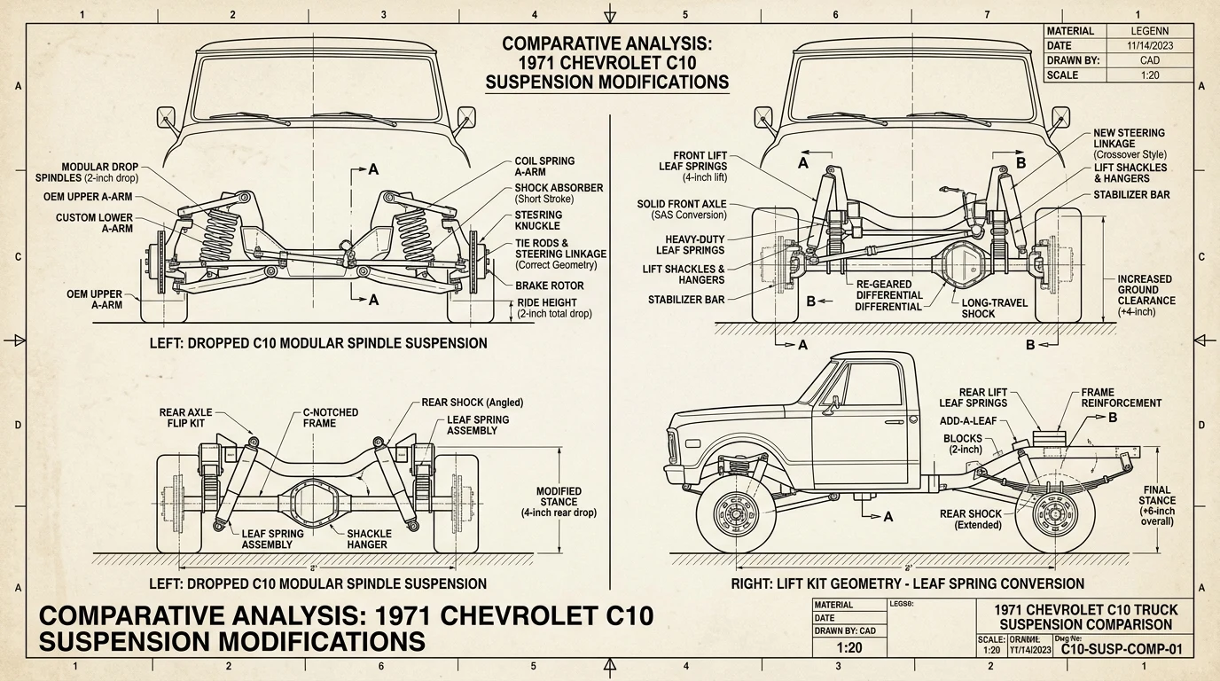
Achieving a clean, functional lowered stance on a 2WD C10 Squarebody requires respecting front suspension geometry. The front suspension uses double wishbones with unequal-length A-arms. Lowering by cutting front coil springs causes the lower control arm to point upward at ride height, severely reducing bump-stop clearance and creating progressive bump-steer.
The proper engineering method combines 2.5" drop modular spindles (which relocate the wheel spindle pin upward without altering ball-joint angles) with moderate 1" or 2" lowering springs. In the rear, a rear axle flip kit places the leaf spring beneath the axle housing (a 5" to 6" drop), requiring an axle-relocator bracket to restore pinion angle and a heavy-gauge C-notch welded to the frame rail.
C-Notch Frame Clearance & Flip Kit Estimator
Calculate axle-to-frame travel, determine mandatory C-notch depth (2.5" bolt-in vs 5" step-notch), and verify bed floor clearance before cutting frame rails.
Squarebody Tire Fitment & Wheel Clearance Matrix (Stock to 6" Lift)
Confirmed tire sizes, rim dimensions, backspacing tolerances, and fender clearance limits across factory stock, lowered C10 street stances, and lifted 4WD K10/K20 chassis platforms.
| Suspension Height Stance | Confirmed Max Tire Size | Ideal Wheel Width & Backspacing | Inner Fender & Sway Bar Rubbing Risk | Mandatory Chassis Modifications |
|---|---|---|---|---|
| Factory Stock C10 (2WD) Sec 3C, p. 14GM Service Manual ST-330Section 3C — Front Coil Spring Dimensions Factory Stance Tolerances | 255/70R15 (29.1" × 10.0") | 15×7 or 15×8 (4.00" BS) | Zero rubbing across full steering lock. | None (100% factory original clearance). |
| C10 2.5" Drop (Mild Stance) | 275/60R15 (28.0" × 10.8") | 15×8 (4.25" BS) or 17×8 (4.50" BS) | Slight rub on inner plastic fender liner during hard compression dips. | Drop spindles preserve factory coil spring geometry. |
| C10 4.5" / 6" Drop (Pro Stance) | 255/50R17 (27.0") / 275/40R20 (28.7") | 17×8 (4.50" BS) / 20×8.5 (5.00" BS) | High rub risk on front fender lip; tight clearance to inner bed wheel tub. | Under-bed frame C-notch mandatory; roll front fender lips. |
| Factory Stock K10 / K5 (4WD) Sec 3D, p. 8GM Service Manual ST-330Section 3D — 4WD Leaf Arch Heights Negative Arch Factory Spec | 31×10.50R15 (31.0" × 10.5") | 15×8 (3.75" to 4.00" BS) | Zero rubbing under normal road and mild off-road trail conditions. | None (standard factory 4WD arch clearance). |
| K10 2.5" Lift (Trail Setup) | 33×12.50R15 (33.0" × 12.5") | 15×8 or 15×10 (3.75" BS) | Clears factory sway bar; slight contact on front lower fender fang at full lock. | Slight trim on front bumper corner lower lip. |
| K10 / K20 4" Lift (4.0" All-Terrain Lift / 4 Inch Lift) | 35×12.50R15 / 17 (35.0" × 12.5") | 15×8, 17×9 (4.00" to 4.50" BS) | Generous arch clearance; zero frame contact with 4" backspacing. | Raised steering arm or drop pitman arm; extended brake lines. |
| K20 / K30 6.0" Lift (Severe Duty) | 37×12.50R17 / 38×13.50R17 | 17×9 or 17×10 (4.50" BS) | High drag link bump-steer risk with factory push-pull steering. | Passenger crossover high-steer conversion and CV front driveshaft mandatory. |
4WD Lift Geometry: Curing Squarebody Bump-Steer
Factory 1973–1987 4WD GM trucks (K10, K20, K30, K5 Blazer) utilize solid front driving axles (Dana 44 or GM 10-bolt, with Dana 60 on 1-tons) suspended by semi-elliptic leaf springs. The factory steering system uses a longitudinal push-pull drag link connecting the steering gear pitman arm to the driver-side knuckle.
When suspension height is lifted 4 inches or more, the steep drag link angle causes the axle to swing through an arc that violently steers the front wheels whenever the suspension compresses over bumps. Installing a passenger-side crossover steering conversion with an 1.5" DOM cross-chassis drag link neutralizes bump-steer and restores modern highway tracking.
Frequently Asked Suspension Lift & Drop Questions
01 Why should you use drop spindles instead of cutting coils on a C10?
Drop spindles (such as 2.5" dropped cast-iron spindles) lower the vehicle by moving the wheel pin center upward relative to the ball joint locations. This lowers the truck while preserving 100% of factory suspension travel, factory coil spring rates, and original steering geometry. Cutting coils reduces suspension compression travel, causes bottoming out on bump stops, and creates severe negative camber.
02 When is a frame C-notch required on a lowered C10 Squarebody?
A bolt-in or welded frame C-notch is mandatory whenever the rear axle is lowered 5 inches or more (such as when installing a rear axle flip kit, which relocates the axle tube on top of the leaf springs for a 5" to 6" drop). Without a C-notch, the axle tube will slam into the factory frame rail bottom flange on normal road bumps.
03 What is crossover steering and why is it required on lifted 4WD K10/K20 trucks?
Factory 1973–1987 4WD GM trucks utilize a push-pull steering geometry where the drag link travels front-to-back from the steering gear box to the driver side steering arm. With lifts over 4 inches, the steep drag link angle causes severe bump-steer (the steering wheel violently jerks when suspension compresses). Crossover steering mounts a passenger-side high-steer arm and routes the drag link side-to-side, neutralizing suspension geometry.
04 What tire sizes fit factory Squarebody trucks with 2", 4", and 6" lifts?
Stock suspension clears 31x10.50R15 tires. A 2.5" lift clears 33x12.50R15 tires on 8-inch wide wheels. A 4.0" lift clears 35x12.50R15 or 35x12.50R17 tires with zero fender trimming. A 6.0" suspension lift clears 37x12.50 tires.
Squarebody Engineering Architecture & Technical Pipeline
Complete subsystem hierarchy modeling powertrain, drivetrain ratios, factory electrical, and Phase 2 sister tools.
Powertrain & Small/Big Block Engine Specs
CID, horsepower, compression ratios, firing order, and valvetrain tolerances for 250, 305, 350, 400, and 454.
Automatic & Manual Transmission Ratios
TH350, TH400, 700R4, and SM465 continuous highway RPM, gear ratio, and rolling tire diameter solver.
Universal 13/17-Digit VIN & SPID RPO Decoder
ISO 3779 dual-format decoder for model year, assembly plant, GVWR series, and factory options.
Factory Electrical & Bulkhead Wiring Pinouts
1973-1987 firewall bulkhead connector pinouts, GM color standards, wire gauges, and ignition circuits.